Quick Start Guide Pannoramic SCAN II
Principle
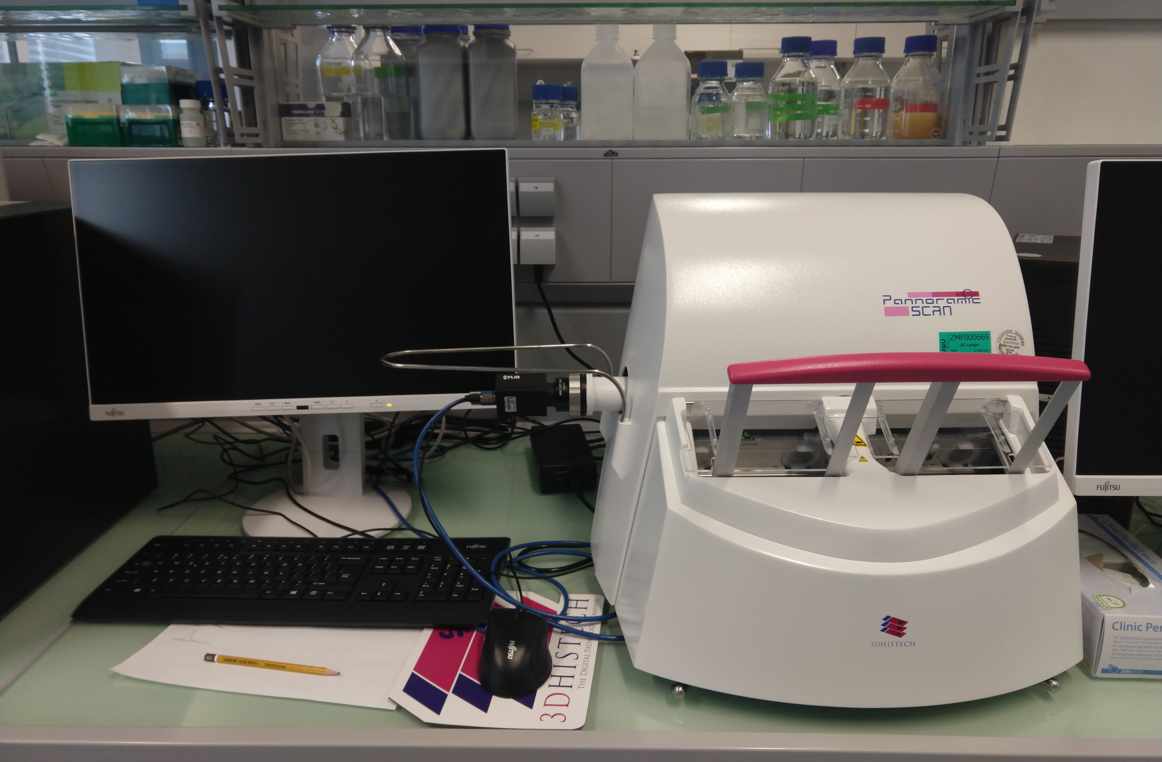
The Pannoramic SCAN II is designed to digitise biological specimens and preparations (typically histological sections) using transmitted light.
The scanner can be used in two modes:
- Microscope mode (to scan individual slides).
- Planner mode (to scan whole trays or multiple trays)
Specifications
The scanner can be used with slides and coverslips that meet the following specifications:
| Slides | Coverslips | |
|---|---|---|
| length | 75.0 to 76.0 mm | max. 50 mm |
| Width | 25.0 to 26.0 mm | max. 24 mm (recommended: 22 mm) |
| thickness | 0.90 to 1.2 mm | No. 1 and No. 1.5 (0.13 to 0.16 mm and 0.16 to 0.19 mm) |
| Corners | 45° bevelled corners | |
| Edges | Sanded or cut |
Slides covered with foil can also be used.
Slides covered with varnish must NOT be used. This is possible in principle, but the unit would have to be readjusted. If necessary, please contact Sabina Köfler.
General
With H&E staining, the contrast is very good and hardly any manual adjustment is required.
With IHC slides the contrast is worse. These slides therefore require more manual intervention.
There are two programmes that are used:
- Pannoramic Scanner Control Software (the software that controls the scanner).
- Pannoramic Viewer Software (also called SlideViewer - for viewing and annotating the scans). SlideViewer can be installed on any private computer (download: https://www.3dhistech.com/research/software-downloads/).
No keyboard shortcuts can be defined in SlideViewer. There are only a few that are hard-coded. An overview can be found in the Settings under Keyboard → Overview.

Important:
Do not make any changes to the settings in the Settings.
Preparation
When mounting the section on the slide, make sure that there is some distance to the object at the left edge, as the slide lies there in the rail and thus a part of the slide is covered by it.
Start-up
First steps
Scanner and PC can run independently, but the scanner must be switched on before starting the software.
- Start the Pannoramic Scanner Control software.
select mode → Microscope mode/Planner mode/Settings (icons).

initialise microscope (3rd button from top left)

select scan profile (e.g. 20x H&E)
- Either one of the existing profiles can be selected, or
the profile of an already scanned slide can be used


load slide(s)
- Left slide for loading, right slide for unloading.
- Before inserting the slides, they must be checked for compatibility. To do this, measure the height, width and thickness (without cover slip) with the stainless steel tool.
 All in the green zone? OK
 - Load the cassette from right to left. Note the direction of the labelling. There is a note on the side of the magazine indicating how to load the slides.
Open the Slide Control Display
 The order in the SlideManager Control Display is from left to right, but in the cassette the first slide is the one on the far right.
Working in Microscope mode
Left side → Menu for scanner
Option: Scan separately (deactivated by default) possibly necessary for prostate biopsies → all objects on the slide are numbered individually.
After successful scanning, a link to the scan appears at the top right. Click on the link to open the scan in SlideViewer.
z-stack
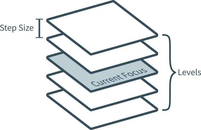
Step size = 0.2 µm (x value in the field) → this is the distance between the recorded levels of the z-stack.
For example, if you set 5 levels, the output level (current level) plus four (two focus levels above and below) will be captured.
Therefore, it is advisable to choose an odd number for the focus levels.
If you know the thickness of the section, you can calculate the maximum number of focus planes (levels):
= thickness of the cut (e.g. 2 µm)
= Step size (min. 0.2 µm)
= Number of possible focal planes (levels)
Or vice versa:
If you know how many focal planes (n) you want to take, you can calculate the factor x by which you have to multiply the step size:
So with 5 focus levels, the factor x is 2.
Important:
The z-stack option "Extended focus" combines the individual images into one overall image → Caution: Loss of information.
The preview window
Around the preview window there are several settings, e.g. Automatic Threshold (for automatic tissue detection, etc.) or for manually creating a frame around the tissue to be scanned.
Working in Planner mode
In the upper right corner + or - to add or delete individual racks.
Specify Range to skip (the slots in the rack that are not occupied) → confirm with +.
A scan profile can either be applied to all racks (see image red frame), to all slides of a single rack (see image yellow frame) or to each slide individually.

At the bottom right, in the blue-turquoise rectangle, go to Microscope mode.
Load your settings through a .csv file
The most convenient way to load a scan profile for a large number of slides is via a .csv document. Simply create a document in advance with the following data:
An example document consisting of a rack with 5 slides could look like this:
| rack number (1-6) | slide position (1-25) | desired file name | barcode (optional) | profile name | illumination type (BrightField) |
|---|---|---|---|---|---|
| 1 | 1 | MyFileName1 | 123ABC | HE_20x_excellent | BrightField |
| 1 | 2 | MyFileName2 | 245DEF | HE_40x_excellent | BrightField |
| 1 | 3 | MyFileName3 | 678GHI | HE_40x_zstack_excellent | BrightField |
| 1 | 4 | MyFileName4 | 987JKL | IHC_20x_excellent | BrightField |
| 1 | 5 | MyFileName5 | 654MNO | IHC_40x_excellent | BrightField |
Note: A slide can also be included in the list more than once, for example if it is to be scanned with different profiles.
The finished .csv file must be saved without a header line and with a semicolon as field separator. In the end, it should look like this:
1;1;MyFileName1;123ABC;HE_20x_excellent;BrightField
1;2;MyFileName2;245DEF;HE_40x_excellent;BrightField
1;3;MyFileName3;678GHI;HE_40x_zstack_excellent;BrightField
1;4;MyFileName4;987JKL;IHC_20x_excellent;BrightField
1;5;MyFileName5;654MNO;IHC_40x_excellent;BrightField
Note: If you don't use the barcode option you must not leave an empty column in the .csv file (two semicolons in succession). The file will not load correctly.
These steps are necessary to start the scans.
start the Pannoramic Scanner Control Software
select Planner mode
select storage location
load CSV file

start scan
Working in SlideViewer
In SlideViewer, annotations can be made with various tools.
These are quite self-explanatory, except for the use of the "Closed Polygon" tool, which can be closed with a right click.
Annotations can be selected by clicking on their (yellow) label.
When exporting annotations, remember that only the selected annotation(s) will be exported. With Ctrl + A all can be selected.
At the bottom right of the window there is the Multi View Toolbox. This allows multiple slides to be viewed simultaneously in a split view.
Working in conjunction with TMA Grand Master
TMA Cores can be annotated in SlideViewer to be used as a template in TMA Grand Master to create the actual cores: → Annotations → TMA Tools → Colour corresponds to the colour coding of the drills.
Reservations
Please make reservations for your scan time via the shared ZMF online calendar.
Cleaning
Cleaning the tools
By heat or wax remover (to be defined).
Maintenance
Contact
The unit is maintained by Sanova. In case of a problem please contact Sabina Köfler immediately.
Troubleshooting
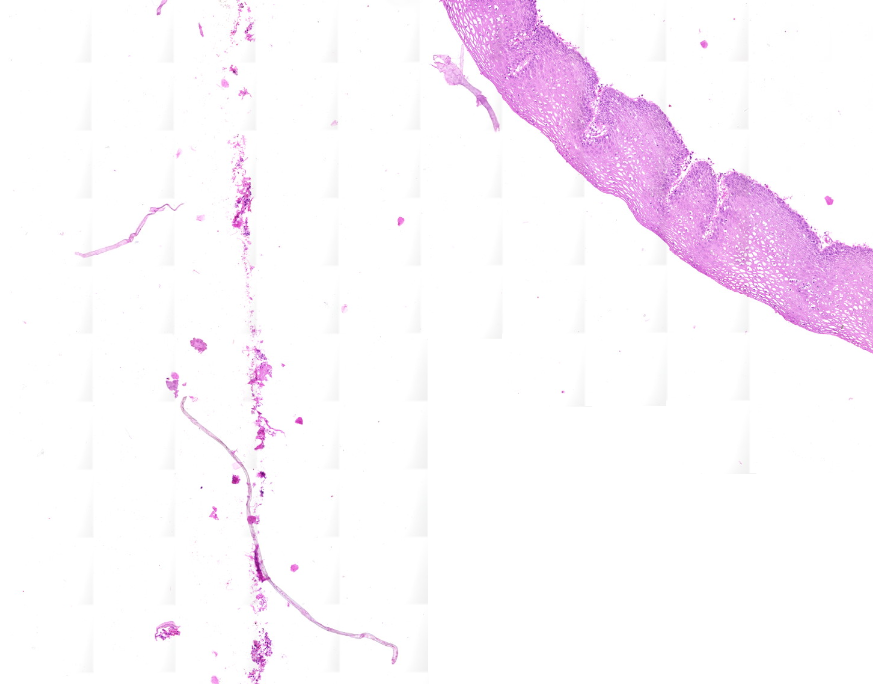
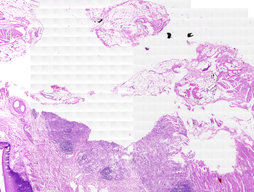
Image artefacts
In case artefacts like those shown in the images below appear you need to check the profile's Image settings > Use saved compensation image. Compensation images are reference images used for white balancing and shading.
If Use saved compensation image is checked, create a new one.
If it is unchecked: make sure that your slide has enough clean background available for the scanner to create a compensation image.
Misc
To open the housing cover, loosen the four screws on the bottom of the housing.
If a scanner error occurs, check the plug connections.
Appendix
Help
The complete manual in English can be accessed directly via the software.